



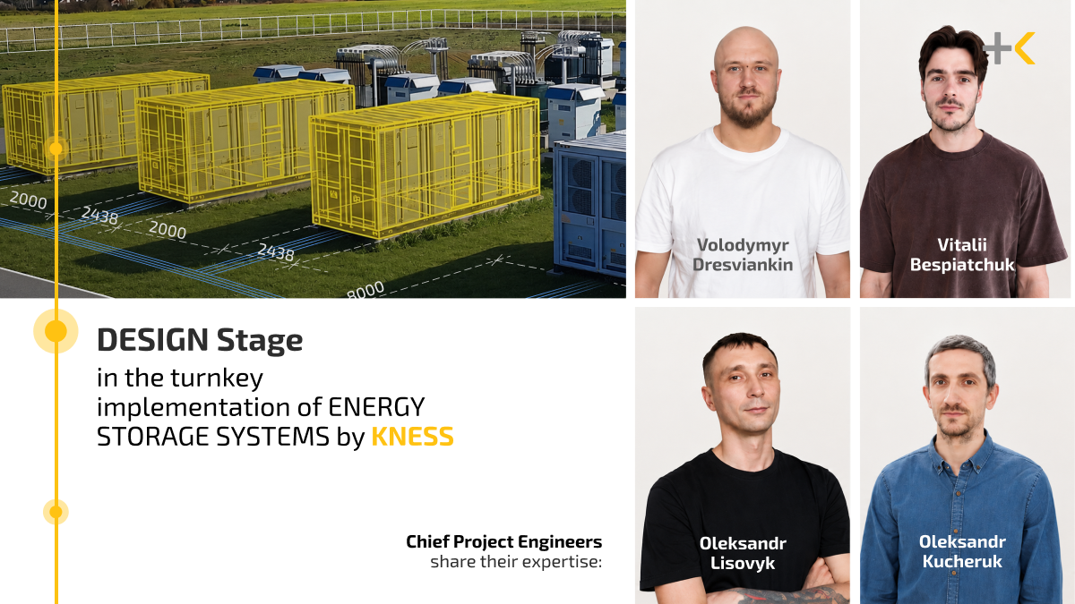
Engineering opens the cycle of services under the EPC contract through which KNESS implements turnkey energy storage system (ESS) projects. This stage has its own specifics. It is crucial to take into account the future facility’s operating scenarios, equipment configuration (PCS and ESS container parameters), fire safety, the possibility of integrating monitoring and control systems, and more. KNESS’s project portfolio includes 830 MWh of energy storage system capacity, more than 200 MWh of which is already successfully operating in the market. Together with KNESS Chief Project Engineers Vitalii Bespiatchuk, Oleksandr Lisovyk, Volodymyr Dresviankin, and Oleksandr Kucheruk, we share our expertise on how to properly design an efficient ESS facility.
The design stage can be divided into two parts: development of the “Design” documentation (Stage P) and development of Detailed Design Documentation (Stage R). Stage P answers the questions: “What exactly are we building, where, with what parameters, and how can it be implemented?” Stage R answers the question: “How exactly should the equipment be manufactured, properly installed, connected, and commissioned?” Chronologically, Stage P may be carried out in parallel with development. Stage R begins after all permits and the necessary approvals from the system operators have been obtained. How does the project move at each of these stages?
Development of “Design” Documentation (Stage P): First Steps
- Preparing the design specification for the future construction project
At Stage P, the overall concept of the facility is defined and becomes increasingly detailed with each subsequent step. First, the Chief Project Engineer, together with ESS design specialists, analyzes all available information about the site of the future ESS facility: the distance to the connection point, land-use restrictions, protected areas, easements, proximity to residential developments, and historical climate data. All collected input data — and, most importantly, the ESS usage scenarios — are described in the design specification, as they will determine all subsequent design solutions.
“At this stage, two points are particularly important. First, nominal power and capacity should not be confused, as these are different technical characteristics of an ESS. Second, facilities with the same nominal power may have different equipment configurations and ESS capacities. This depends on the investor’s objectives — whether the ESS is intended for energy arbitrage and/or the provision of ancillary services (FCR/aFRR), or for self-consumption.
KNESS team of developers and design engineers meets the investor’s need for optimal technical and design solutions by selecting the equipment configuration that will be most efficient for the specified operating scenario,” emphasizes Vitalii Bespiatchuk, Chief Project Engineer at KNESS.
- On-site survey of the potential ESS site
- Engineering geodetic and geological surveys
Next, the design engineers conduct an on-site survey to ensure that all site-specific factors are taken into account in the ESS project plan. They assess the terrain, vegetation, flood risks, and the availability of access roads — or the possibility of constructing them — for the delivery of oversized equipment, among other factors.
“The next steps further refine the project details and add depth to the overall picture. Surveyors map all coordinates and site zoning, preparing the topographic base for the general layout, and identify existing utility networks that may interfere with project implementation. Geologists assess the bearing capacity and physical characteristics of the soil, corrosion risks, and groundwater levels to prevent issues after construction, such as subsidence, tilting, flooding, or equipment damage caused by its weight or incorrectly selected materials. The key task at this stage is to identify all limiting factors that may ‘interfere’ with the implementation of the ESS project and take them into account in the subsequent design documentation,” explains the expert.
Next Steps and Technical Solutions
- Preparation of the main electrical diagram and electrical engineering solutions
- Development of the “Relay Protection and Automation and Automated Process Control System” section (RPA and APCS)
- Development of the “Architectural and Construction Solutions” section
“The core of the project is the single-line electrical diagram, which shows the sequence of the ESS connection to the grid and the key equipment parameters. This is where the entire operating logic of the facility is defined. That is why these design solutions are developed by our team of engineers who specialize specifically in energy storage system projects,” comments Oleksandr Lisovyk, Chief Project Engineer at KNESS.
Once the equipment has been selected and the single-line diagram prepared, the design engineers develop the facility layout, while the RPA and APCS specialists develop conceptual solutions for equipment protection — including the composition and types of protection, short-circuit current calculations, and protection settings — as well as data transmission, including its structure and type.
Civil engineers then begin their work. Based on the electrical layout and the geodetic and geological surveys, they perform calculations to determine the appropriate type and dimensions of foundations.
Development of Further Documentation
- Environmental Impact Assessment (EIA)
- Development of general layout and transportation solutions
- Development of the General Explanatory Note (GEN) — covering technical and economic indicators and calculation of the consequence class — and the Construction Organization Plan (COP)
The Environmental Impact Assessment describes the potential presence of hazardous substances in the designed equipment and the measures required for its safe operation. The general layout is then developed, specifying solutions for site grading, the arrangement of utility networks, and landscaping of the construction site. The General Explanatory Note and Construction Organization Plan are prepared separately.
“The project must provide appropriate conditions for the delivery and installation of oversized equipment, its correct placement on site in compliance with all safety and fire protection requirements, as well as sufficient clearances for convenient maintenance and installation,” comments Oleksandr Kucheruk, Chief Project Engineer at KNESS.
It is also essential to properly design the fire protection systems.
“Lithium-ion batteries, which form the basis of most modern energy storage systems, are prone to thermal runaway — a self-sustaining overheating reaction that is difficult to stop using conventional fire suppression methods. Therefore, during the design phase, we incorporate systems for early detection of gas, smoke, and temperature, automatic fire suppression, ventilation for the removal of hazardous gases, physical separation of modules to prevent fire propagation, as well as measures to maintain the required safety distances from adjacent facilities and residential areas. Fire safety is a priority in ESS projects,” explains Oleksandr Kucheruk.
- Development of the ESS Grid Operating Modes Analysis section
“All requirements for the development of design documentation are ‘hidden’ in the Technical Specifications (TS). That is why we review the TS as thoroughly as possible to ensure that no important sections are overlooked, as without them, approval by the system operators would not be possible. One such requirement may be an assessment of the impact of adding ESS capacity to the power grid. We perform this assessment in a dedicated section — the ‘ESS Grid Operating Modes Analysis’,” the expert explains.
Equipment Selection for the Project
- Preparing equipment questionnaires to obtain commercial proposals
This is the most important stage for selecting the right equipment.
“For complex technical facilities such as energy storage systems, there is no one-size-fits-all set of technical solutions, and an error in equipment specifications can be extremely costly. To make the optimal choice, we prepare a standardized questionnaire for suppliers and obtain comparable, customized commercial proposals with the most detailed technical descriptions of the equipment possible. We then engage extensively with our partners to clarify all details, review the latest market developments, conduct an in-depth comparison, and make the final decision,” notes Volodymyr Dresviankin, Chief Project Engineer at KNESS.
For ESS container selection, KNESS cooperates with its strategic partner HITHIUM, one of the world’s leading energy storage system manufacturers. For other equipment, we have also been working directly for decades with other global manufacturers included in the Tier 1 ranking.
Approval and Expert Review
- Approval of design documentation by the Distribution System Operator (DSO) and Transmission System Operator (TSO)
- Expert review of the project documentation, if required
“Once the necessary package of documents has been prepared, we submit it for approval to the TSO and DSO. In some cases, an expert review of the project is also required — for example, when the facility falls under consequence (responsibility) class CC2 or CC3 and/or is located in an area of increased seismic activity. We separately develop and obtain approval for the TSO or DSO grid reconstruction design required for the ESS connection. The development of designs for the linear infrastructure required to connect the ESS to TSO or DSO grids at voltage levels of 110/35/10 kV is also within our team’s expertise. Approval of the complete set of the above-mentioned designs confirms that the ESS can be connected to the grid from both a technical and operational perspective,” summarizes Volodymyr Dresviankin.
Development of Detailed Drawings (Stage R)
- Development of detailed design documentation packages and issuance of manufacturing specifications to factories for equipment production (panels, outdoor enclosures, distribution devices, switchboards, etc.).
“Stage R is when the ‘concept’ is broken down into specific solutions for the manufacture, construction, installation, commissioning, and operation of all equipment as a single integrated system,” says Volodymyr. At this stage, every detail is carefully designed and documented to ensure that the protection logic corresponds to the parameters of the selected equipment, the designed support structures allow the equipment and outdoor enclosures to be installed correctly, and there is sufficient space for cable routing and connections. Based on the manufacturing specifications issued to the factories, the required equipment is procured.
All sets of design documentation are then handed over to the construction team for implementation of the ESS facility. If required, the design engineers provide designer supervision during construction to ensure that each section of the project is implemented in accordance with the specified design solutions.
More about the next stages of the EPC cycle, as well as further maintenance and commercial management of ESS facilities, will be covered in upcoming materials.


